Jan HusakPortfolio 2026
P.02 / Machine design

Gear reducer

Design, sizing and CAD of a three-stage right-angle industrial reducer: one straight bevel pair and two spur pairs, taking 75 kW down to 40 rpm.

Date
June 2025, reviewed October 2026
Context
Laboratorio CAD, Politecnico di Milano
Team
Two students, with Moreno Fumagalli
Tools
MATLAB, PTC Creo
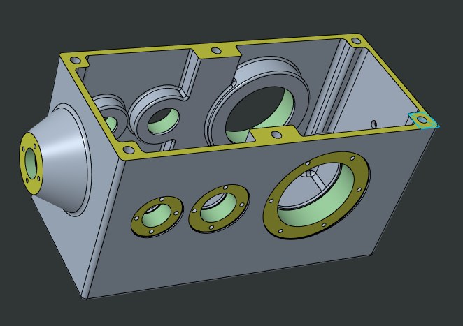
Cast housing of the reducer with machined faces highlighted
Fig. 1 / Cast housing. Machined faces in yellowPTC Creo
01 / Brief

The specification

Deliver 17,400 N·m at 40 rpm with an efficiency of 0.975 to 0.985 and a 30,000 hour service life, in a right-angle B3 layout.

The deliverables were the full sizing calculations, a parametric MATLAB model, a Creo assembly with detail drawings, and a housing that can actually be cast and machined.

MotorSMEM 7SM3 315, 75 kW at 990 rpm
Total ratio25, split as 2.5 (bevel) x 2.5 x 4
StagesStraight bevel pair, then two spur pairs
Modules10 / 10 / 12 mm (ISO 54)
Output torque17.4 kN·m at 40 rpm
Bearing life30,000 h target
02 / Design

What we designed

I wrote the MATLAB script that sizes the whole drive train. Gears are sized for tooth bending with Lewis, shafts are modelled as beams on two bearings and checked with von Mises, and bearings are chosen from the SKF catalogue and checked for L10 life.

The assembly was modelled in PTC Creo, including the cast housing with a lifting eyebolt and an oil level indicator, and all the detail drawings. The housing drawings mark which faces are milled and which are bored after casting.

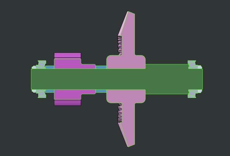
Section of the intermediate shaft with bevel wheel and spur pinion
Fig. 2 / Shaft 2: bevel wheel and spur pinion
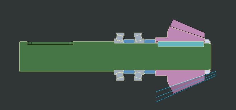
Section of the input shaft with the overhung bevel pinion
Fig. 3 / Shaft 1: input, overhung bevel pinion
03 / Review

Going back to it a year later

In October 2026 I re-checked every calculation from the original project. The force model had errors, and some loads were up to 30 times too high.

Spur radial forces had been computed as Ft / tan α instead of Ft · tan α, the bevel wheel force components were swapped, and the output gear force used the pinion diameter. I rebuilt the loads from a full 3D shaft model. On the in-line intermediate shafts the two tangential forces add instead of cancelling, and the axial force on the overhung bevel pinion reduces the bending moment at the bearing.

With the corrected loads, gears and shafts still pass. Four bearing positions did not reach the 30,000 h life, and a surface pressure (pitting) check showed through-hardened steel was not enough for stages 2 and 3.

ShaftsAll four verified with corrected loads
Gear steelMoved to case-hardened 18CrNiMo7-6 after the pitting check
Shaft 2 bearingsPair of 32314 J2/Q, over 170,000 h
Shaft 3 bearingsNUP / NU 2218 ECP, about 59,400 h, same bore and outer diameter
Bevel face width90 to 80 mm, bending check still met